Installation of the geothermal heat pump and buffer in Amadeo
| 04 November 2009 - Comments (0) | Construction |
 We covered so far, the installation of the vertical geothermal probes and the connection of the probes to the geothermal heat pump. In this article, we look at the installation of the pump as a complete system. We look at the filling of the probes, the insulation of the pipes and the various connections to the different sub-systems.
Amadeo geothermal system
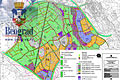
The geothermal system installed in Amadeo is based on 5 vertical geothermal probes. Each geothermal probe goes 100 meters underground. Those 5 probes are then connected together to form one large vertical closed loop. As each vertical probe is made of 2 vertical loops, the total length of the aggregated closed loop with the probe extensions is more than 2 kilometers : 5 probes x 2 loops x 200 meters (100 meters down + 100 meters up).
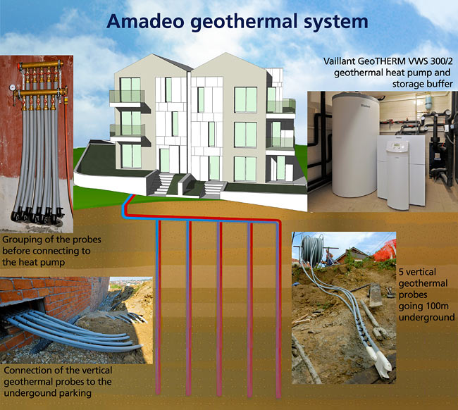
Amadeo geothermal system (illustration Beodom).
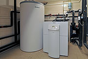
Inside of the building, the geothermal system is powered by a Vaillant geothermal heat pump, GeoTHERM VWS 300/2, that delivers 30kW. The pump is connected to a storage buffer with a capacity of 750 liters. The role of the buffer is to optimize the functioning of the heat pump by storing large amount of energy in the form of hot water.
The heat pump provides hot water for the underfloor heating system of Amadeo. It also provides hot water to a secondary circuit that can be connected to a fan-coil in each apartment. Last, the heat pump provides the secondary energy used to warm up sanitary hot water. The primary energy for heating up sanitary hot water in Amadeo is the solar system.
In the summer months, the heat pump can be reversed to provide passive cooling for the underfloor system and the fan-coil system.
Installation of the geothermal heat pump
The biggest job by far was the installation of the geothermal heat pump and the connection of all the sub-systems. That part was done by our installer in collaboration with Vaillant.
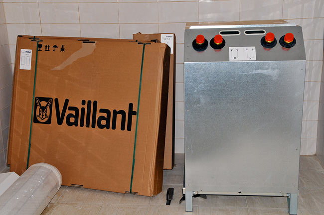
Vaillant geothermal heat pump GeoTHERM VWS 300/2 just delivered and seen from the back of the pump (photo Beodom).
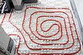
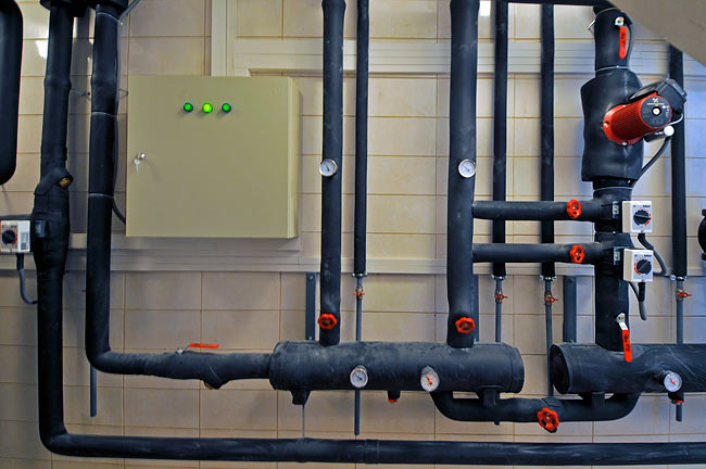
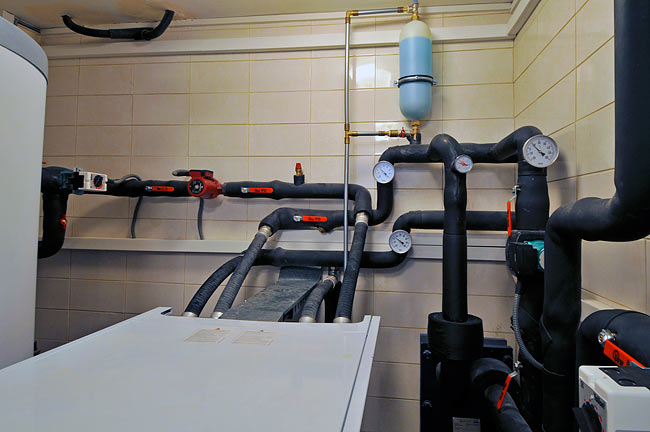
Pipes connecting all parts of the system had to be positioned and installed together with the circulation pumps and valves. The result is an impressive grid of interconnected pipes.
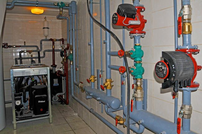
Pipes connecting all parts of the geothermal system (photo Beodom).
Amadeo having 2 independents sides, we have 2 loops for the underfloor heating distribution and 2 loops for the fan-coil distribution (8 pipes).

Connection of the geothermal system to the central distribution in Amadeo (photo Beodom).
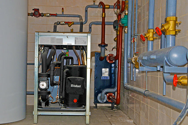
Vaillant heat pump being installed with the passive cooling heat exchanger and circuit on the right (photo Beodom).
The geothermal installation is equipped with a backup electric resistance that can provide additional electric energy when the heat pump cannot provide enough. That could happen during the few coldest days of a given year. Below the electric resistance, is the loop connecting the heat pump to the sanitary hot water system.
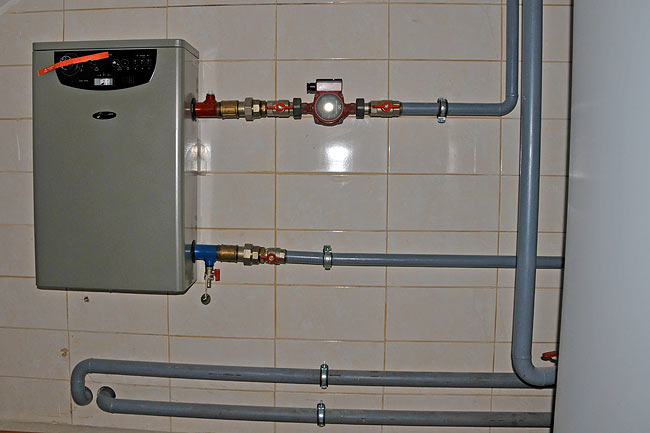
Backup electric resistance and connection to the sanitary hot water system (photo Beodom).
Insulation of the pipes
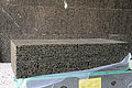
To prevent great heat loss in the garage where the geothermal heat pump is installed, all pipes have to be well insulated. We used Armacell Armaflex AC for the job.

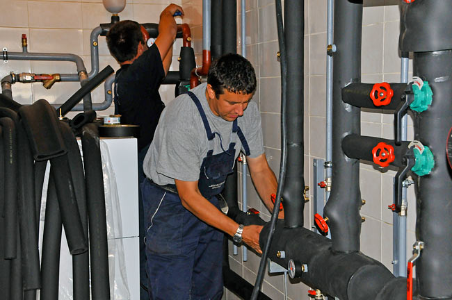
Insulating pipes with Armacell Armaflex AC (photos Beodom).
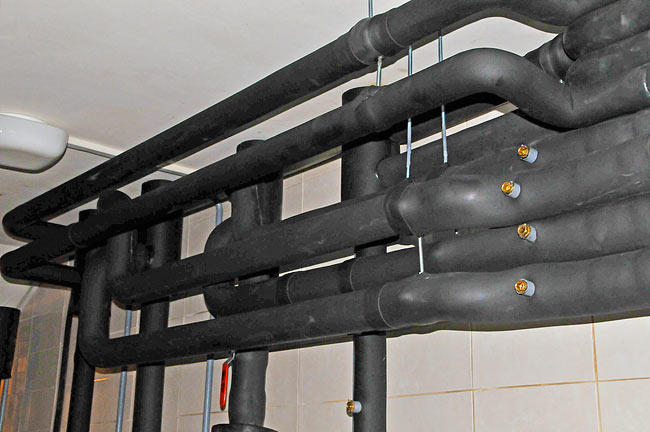
Distribution pipes once insulated (photo Beodom).
Filling of the geothermal probes with glycol
Geothermal probes had been filled with water during their intallation. In the running geothermal system, probes have to be filled with a mixture of water and ethylene glycol to prevent any chance of freezing in the probes. That mix of water and ethylene glycol is the fluid that transports heat through the use of the geothermal heat pump.
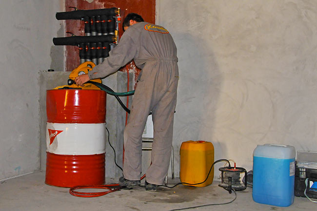
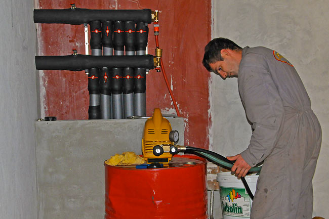
Filling geothermal probes with a mixture of water and ethylene glycol (photos Beodom).
The filling is done one probe at a time, by playing on the valves installed on each end of each probe.
Unlike the geothermal probes, the rest of the geothermal system (buffer and distribution loops) is filled with simple water.
Electric installation
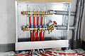
A specific electric cabinet was installed to gather all electric connections. The circulation pumps and mixing valves, as well as the heat pump itself and the backup electric resistance all need to be powered.
The electric cabinet of the geothermal system with the electrical connections to the circulation pumps and mixing valves (photo Beodom).
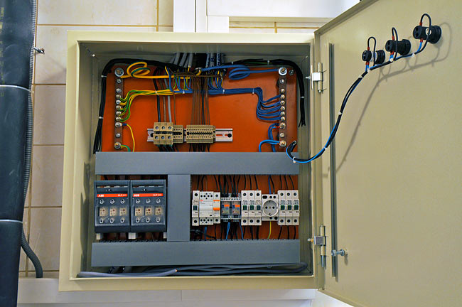
Detail of the electric cabinet of the geothermal system (photo Beodom).
Measuring devices and probes
On several strategic positions, pressure and temperature gauges have been installed. They give an immediate feed back on the running system. Temperature probes are also installed to provide feed back to the heat pump and to the recirculation pumps.
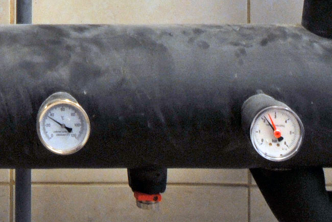
Temperature and pressure gauges on the returning part of the distribution loop (photo Beodom).
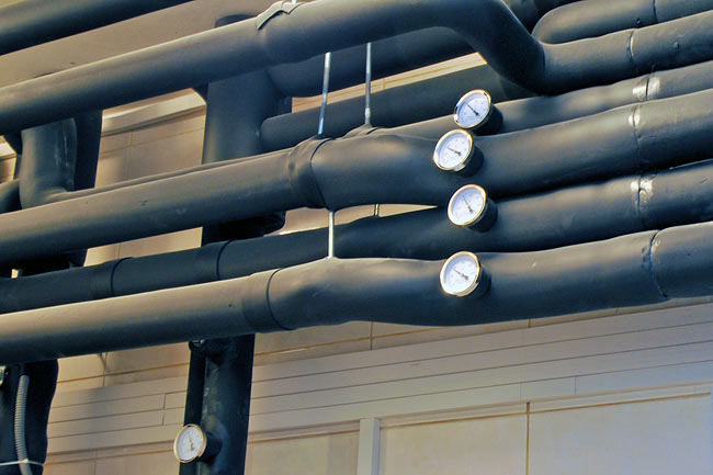
Temperature gauges on the distribution pipes (photo Beodom).
Finished system
Here is the finished and running system in a few pictures and one video. On the video, the background noise is simply the noise from the heat pump running.
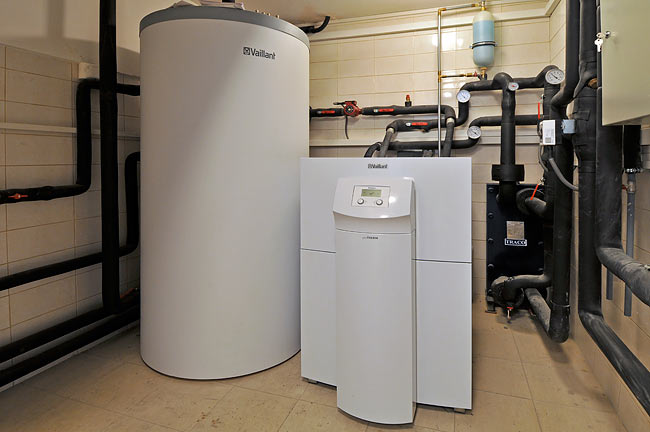
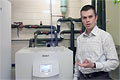
The heat pump and buffer installed and running (photo Beodom).
Connections to the heat pump : one loop for collecting energy from the ground (2 pipes on the left) one loop for energy distribution (2 pipes on the right) (photo Beodom).
In the last article of the serie, we will explain the functioning of the heat pump.